Peeling machines
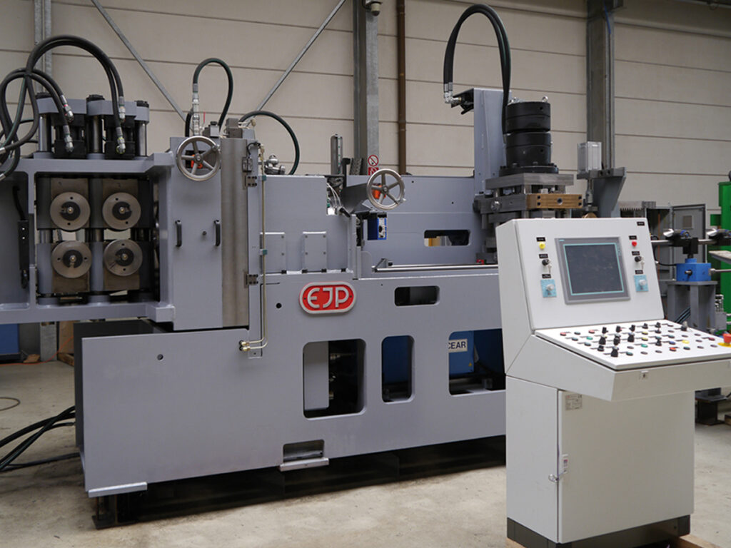
PM series
The PM series is based on the latest developments and features the unique, patented PM peeling head.
In contrast to all competitor systems, the PM peeling head adjustment is rotary and therefore enables maximum stability, regardless of the machined diameter. In the PM series, the compensation of the cutting insert wear occurs automatically. A laser measuring system is used for this purpose.
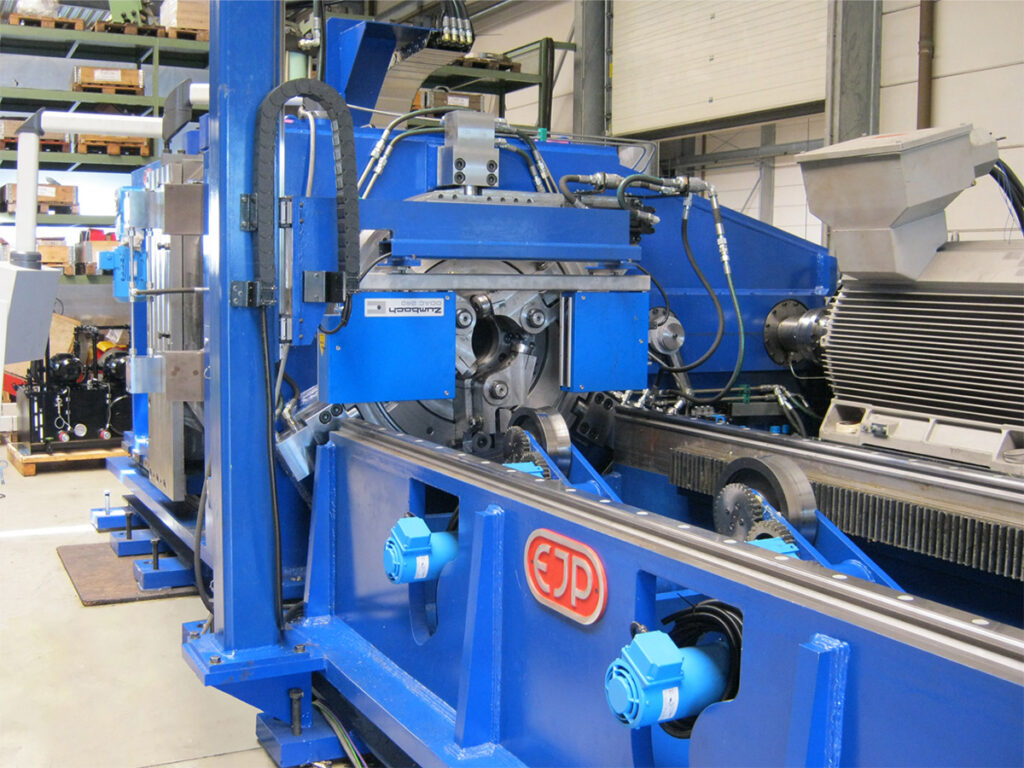
The system components
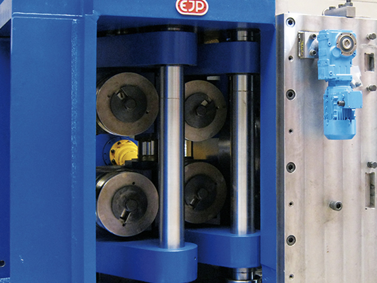
Feeding unit
The feeding unit consists of four large rolls driven by servomotors.
The drive takes place directly or via a distribution gearbox. This results in a precise synchronization of the material feed with the pull-out carriage. This is also driven by a servomotor. Hydraulic cylinders with servo valves ensure precise and powerful holding of the material to be peeled. The hydraulic pressure can be set from the control panel and is stored in the recipe control. The rolls are easy accessible for quick replacement.
Inlet guide
The inlet guide is a stable guide system for precise feeding of the black material to the peeling head.
The rolls are made of tool steel to achieve a long service life. The inlet guide has disk spring units to compensate for diameter fluctuations and out-of-roundness of the starting material. The concentric adjustment of the inlet guide is carried out by handwheel or servomotor.
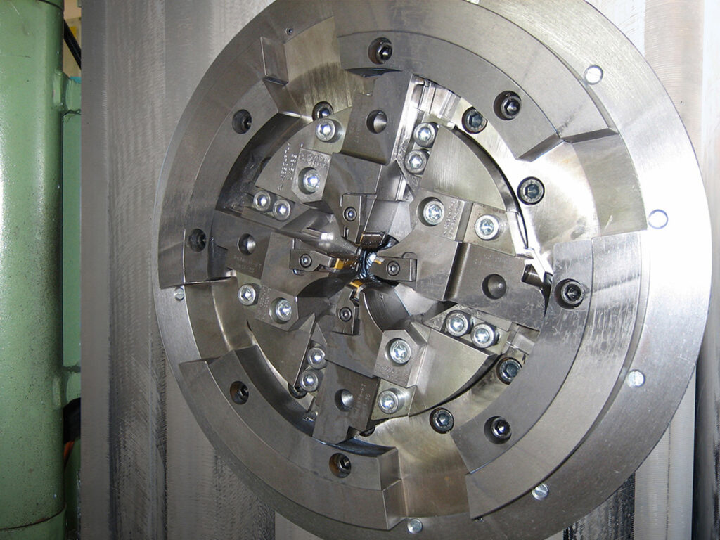
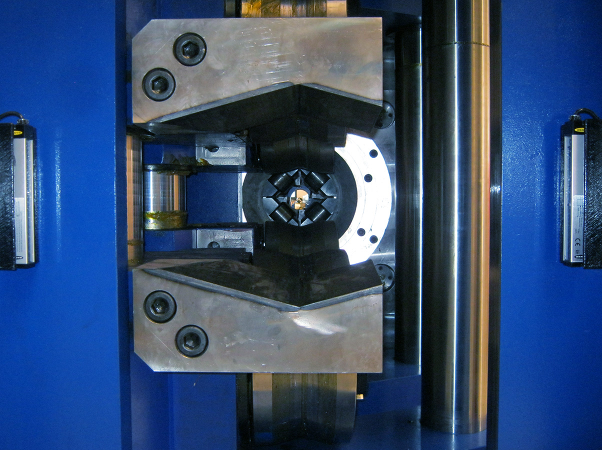
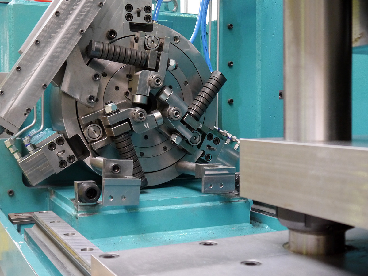
Peeling head with drive and adjustment
The peeling head has an adjustment made by the rotation of the inner ring.
As a result, a unique stability of the tool holders is achieved. These form a line with the mounted replaceable cutting inserts, together with the outer ring of the peeling head and the machine housing. This prevents the usual micro-vibrations. Absolute concentricity of all four tool holders is achieved by dispensing with mechanical adjustment elements on the peeling head. The peeling head is driven by a high-performance gearbox. It is powered by a servomotor.
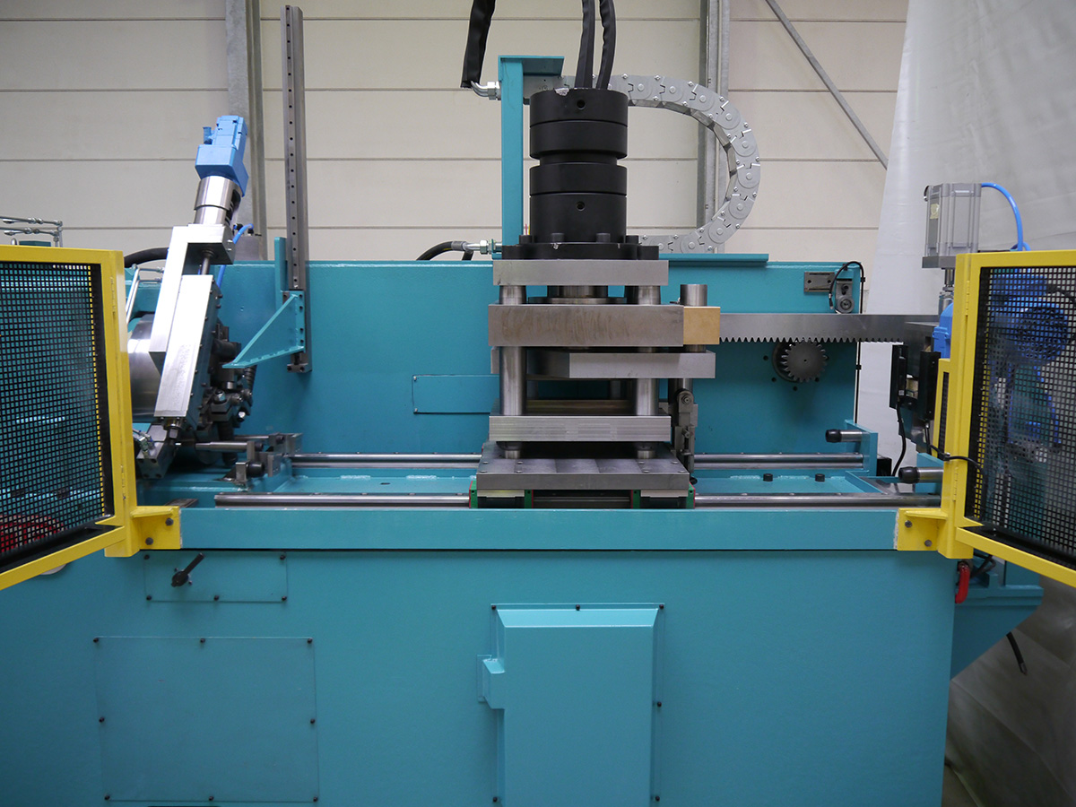
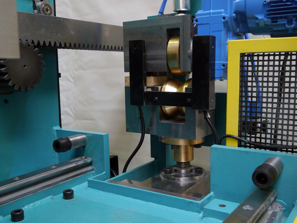
Exit guide
The exit guide serves for the precise guidance of the peeled material after the peeling head.
It has a double material guide. The peeled material is guided directly after the peeling head through shell-shaped sliding shoes made of brass bronze. It is then held in place by rolls made of tool steel before leaving the exit guide. The concentric adjustment of the exit guide is done by handwheel or servomotor.
Laser system
Our peeling machines are equipped with a high precision laser measuring system for permanent monitoring of the peeling results achieved.
With PM peeling machines an automatic compensation of the occurring tool wear takes place. This will ensure that the desired pre-set product tolerance is maintained until the inserts are replaced. For HS peeling systems, the compensation of the occurring tool wear occurs by manual adjustment.
Pull-out carriage
The pull-out carriage has hydraulic cylinders with servo valve for precise and powerful holding of the peeled material.
The hydraulic pressure can be set from the control panel and is stored in the recipe control. Clamping jaws made of polished tool steel ensure damage free clamping of the peeled material. The machine is driven by a servo motor. This enables precise synchronization of the material transport with the slide-in device, which is also driven by servo motors.
Exit pinch roll
The pinch roll consists of two precise rolls, where one of them is driven.
As soon as a bar has left the exit guide, it is taken over by the exit pinch roll. The exit pinch roll is used to transfer the bar to the exit roller conveyor.
Contact us - it's easy.
Your contact person
Managing Director EJP